The following procedures are based on the non-wastegated 1994.5 to early 1999 Garrett TP38 turbocharger, however the later wastegated models are extremely similar. A turbocharger rebuild is typically only necessary when the journal bearings and/or oil ring seals have worn and the turbo is leaking or has excessive shaft end-play. A turbo seal leaking oil on the turbine side typically produces gray smoke and/or oil dripping from the tailpipe. Likewise, a turbo seal leaking oil on the compressor (intake) side tends to produce blue smoke while the engine is running. Excessive end-play of the turbocharger shaft (back and forth movement, not side to side) is also indicative that a rebuild is necessary.
Turbocharger Rebuild Part List
Description |
Part Number |
Turbocharger reinstall kit |
Garrett 468481-0001 |
Turbocharger rebuild kit |
Garrett 472617-0000 |
Compressor housing o-ring |
Garrett 403069-0197 |
Compressor wheel |
BorgWarner 170293 [1] |
High temperature anti-seize |
Motorcraft XL-2 |
[1] - Factory compressor wheel for 1994 to early 1999 model years; compatible with and is an anti-surge upgrade for late 1999 to 2003 model years
How to Rebuild the Turbo on a 7.3 Power Stroke Diesel
Click any thumbnail to view high resolution fullsize image w/ addition details (where applicable)
• Remove turbocharger and place on a clean workbench. See: 1994 - 1999 7.3L Power Stroke turbocharger removal instructions
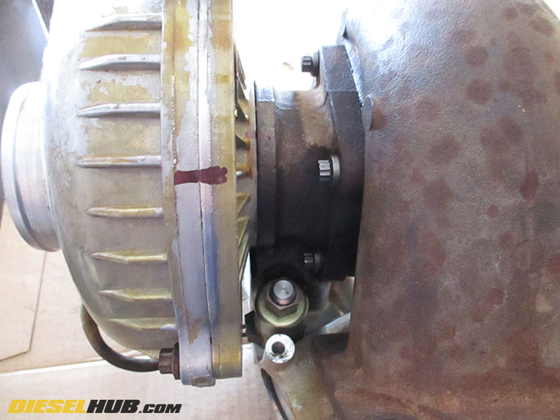
• Mark the following components so that they can be reoriented during reassembly:
1) Compressor housing w/ respect to backing plate
2) Backing plate w/ respect to bearing cartridge/center section
3) Bearing cartridge w/ respect to turbine housing
A scribe or paint pen works well. If you miss this step, it's not particularly difficult to find the correct orientation of these parts during reassembly.
• Remove the exhaust backpressure valve (EBPV) from the turbine housing if it was not removed previously (3 x 8 mm 12 pt bolts).
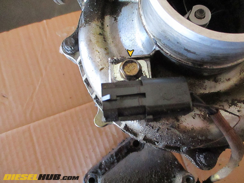
• Remove the retaining bolt for the EBPV solenoid connector with a 10 mm socket.
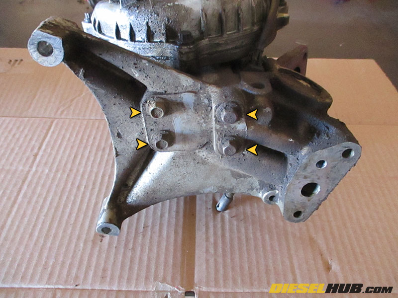
• With the turbocharger on its side, remove the (4) turbocharger to pedestal bolts using a 10 mm socket.
• Separate the turbocharger from the pedestal and set the pedestal aside. If the EBPV actuator assembly is to be rebuilt, see: 7.3L Power Stroke EBPV pedestal rebuild instructions

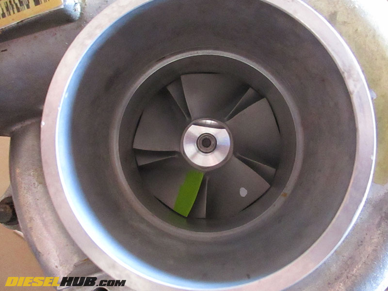
• If the compressor wheel shows any signs of damage or excessive wear around the edge of the blades, it must be replaced. Do not attempt to reuse an excessively worn or damaged compressor wheel. The one pictured here has been severely worn and damaged.

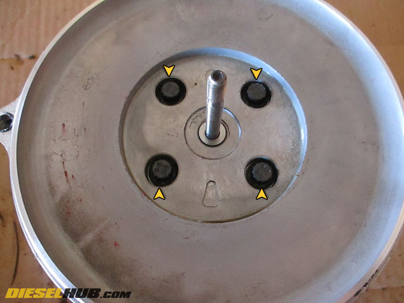
• Remove the (4) compressor to backing plate bolts with a 12 point, 8 mm socket. A 12 point socket must be used as these are not hex head bolts.
• Gently work a razor blade or putty knife between the compressor housing and backing plate. Work it around the circumference of the backing plate until the compressor housing is separated and can be removed. Do not attempt to pry with a screwdriver or other object with a thick tip - there is little clearance between the compressor wheel and compressor housing. Damage can occur if the compressor is forced at a sharp angle. This can be time consuming as the housing may have been sealed with silicon.

• Remove the compressor wheel by holding the turbine wheel with an 18 mm socket and rotating the compressor wheel counter clockwise with a 5/8" or 16 mm socket (it is standard right-hand thread).
• The compressor wheel will slide off the shaft with ease once it is unthreaded completely.
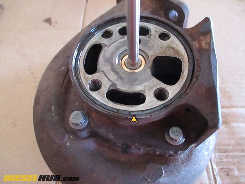
• Remove the (4) compressor backing plate to bearing cartridge bolts using a 12 point, 8 mm socket.
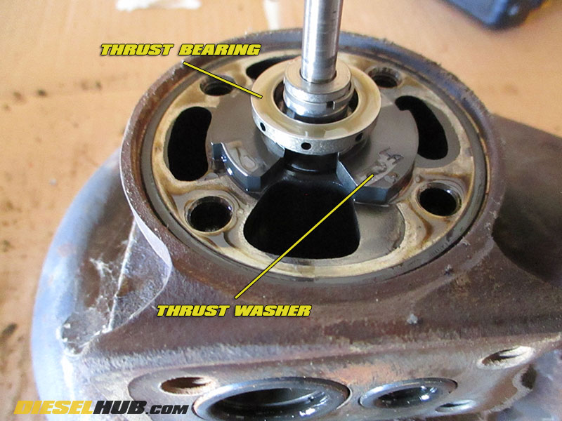
• With the backing plate removed, slide the thrust collar/washer and thrust bearing off of the turbo shaft. Discard these items, they are not reused.
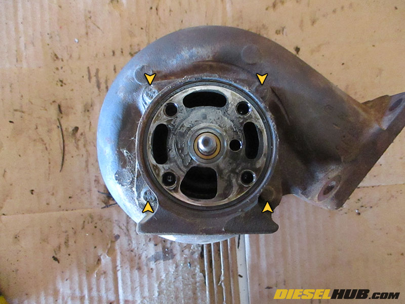
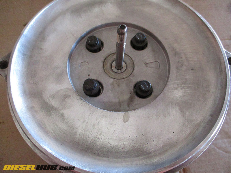
• Remove the (4) bolts securing the bearing cartridge/center section to the turbine housing using a 12 point, 8 mm socket. The center section can be very stubborn and patience is required to make sure that it is removed without damaging the turbine wheel. Like the compressor wheel, the clearance between the turbine wheel and turbine housing is small - if the center section is pried unevenly, the turbine wheel can be damaged. Work around the circumference of the center section using a small screwdriver and dead blow hammer. Tapping the circumference of the center section with a non-marring hammer may also help loosen it. If at anytime the turbine wheel does not spin, it is bound against the turbine housing.
Tip - soak the joint in a liberal amount of penetrating fluid (WD-40, PB Blaster, etc) an hour before removing.
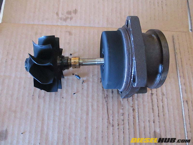
• Once the bearing cartridge/center section has been separated from the turbine housing, slide the shaft out and remove the journal bearings and spacer. The inner journal bearing may have stayed in the center section in which case you'll need to carefully remove it.
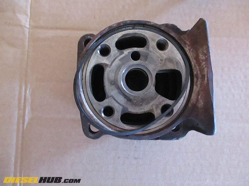
• Remove and discard the bearing housing to compressor backing plate o-ring.

• Remove the oil seal ring on the turbo shaft near the turbine wheel. Two small picks work well at removing the seal without damaging the shaft. Clean any buildup from the shaft where the seal seats.

• Thoroughly clean all sub-assemblies of the turbocharger - bearing cartridge, turbine/compressor housings, compressor backing plate, etc.
• Familiarize yourself with the components included in the turbocharger rebuild kit (refer to details of fullsize image for component labels).
• Install the oil ring seal on the new thrust bearing, being careful no to mar the surface.
• Place the thrust bearing, thrust washer, journal bearings, and journal bearing spacer in a CLEAN container (glass jar, for example). Fill the container with clean engine oil until these components are covered.

• Install the new oil ring seal on the turbocharger shaft (near the turbine wheel), being careful not to scratch/mar the surfaces of the shaft or the oil ring land.
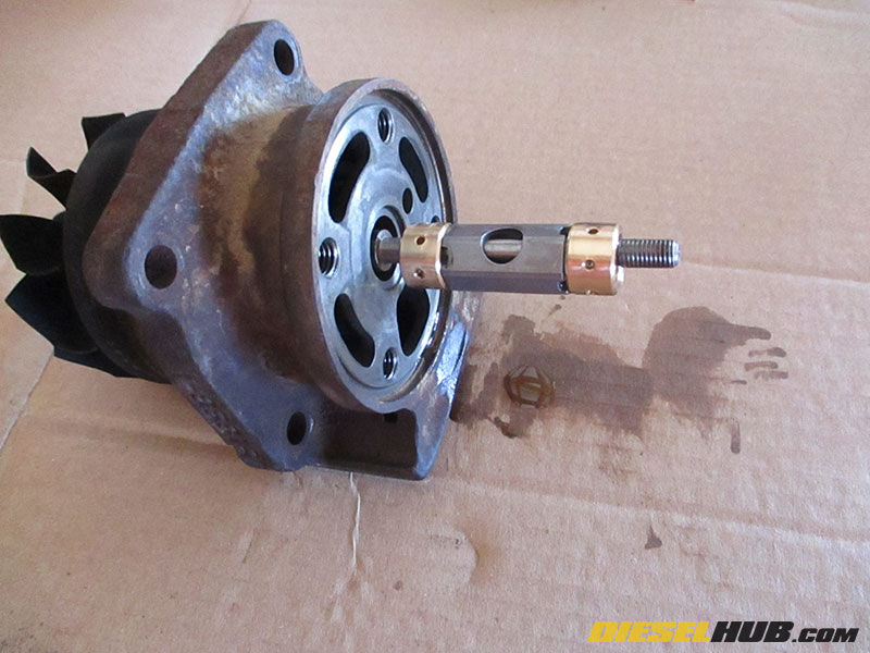
• Reinstall the turbocharger shaft into the bearing cartridge/center section. It will lightly "snap" into place when the oil ring seal near the turbine wheel seats into the center section. Gently pull the turbine wheel away from the center section to verify that it has seated.
• Slide the new, oil soaked journal bearings and bearing spacer onto the turbocharger shaft, then slide them into the bearing cartridge/center section completely.
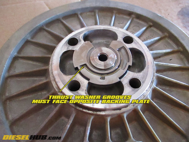
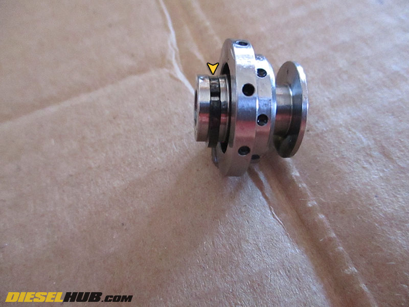
• Slide the thrust washer into the slot of the thrust bearing, then install the thrust bearing into the rear of the compressor backing plate.
Note the orientation of the thrust washer and bearing - the grooved side of the thrust washer must be facing opposite the backing plate and the smooth side should be facing the backing plate. This is critical for lubrication.
The oil ring seal on the end of the thrust bearing installs into the backing plate and "snaps" into place once it is seated. This assembly can only be installed one way so rotate the thrust washer until it matches the indentations in the backing plate.

• Lightly coat the mating surface between the bearing cartridge/center section and the turbine housing with high temp anti-seize (such as Motorcraft XL-2). This is going to act as a mild lubricant to help these two components seat as well as help keep them from bonding together.
• Use the lines/markings you made in the first step to orient the center section to the turbine housing.
• Install and start the (4) bolts by hand. Do not reuse the old bolts, new ones are provided in the rebuild kit. Alternate tightening down each bolt with a socket, about 1/4 turn per bolt, alternating bolts in a cross fashion. This is necessary to keep the turbine wheel from binding! Spin the turbocharger shaft slowly while tightening the bolts down. If at any time it begins to bind, tighten down the opposing bolt. Torque bolts to 30 ft-lbs.
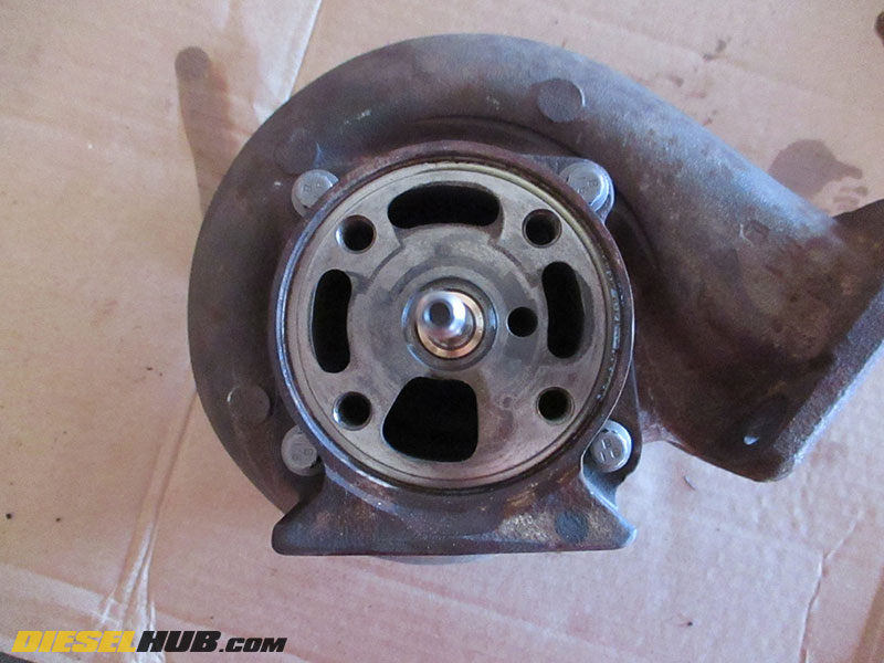
• Coat the center section to compressor backing plate o-ring in clean motor oil, then install it in the corresponding center section groove.
• Install the backing plate. The bolts that mount it to the center section and not oriented symmetrically and thus the backing plate can only be installed one (the correct) way. Torque bolts to 144 in-lbs (inch pounds).
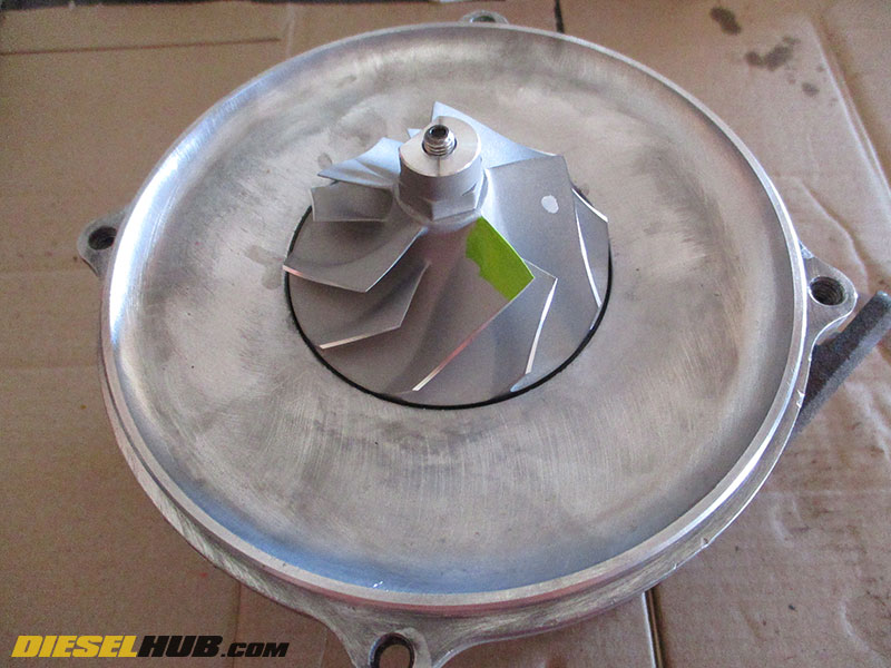
• Thread on the compressor wheel by hand, then torque to 60 - 80 in-lbs. It will self tighten as it rotates and thus the torque spec is not critical so long as it is fully installed. Ensure that the compressor wheel spins freely after installing.
• Install the compressor housing to backing plate o-ring after coating it in clean motor oil.
• Install the compressor housing, orienting it using the marks you made in the first step. Tighten down the bolts slowly after lightly coating them in anti-seize, alternating frequently to avoid binding and damaging the compressor wheel. The compressor wheel and housing have very little clearance; make sure the housing is tightened down evenly. Torque compressor housing bolts to 144 in-lbs (inch pounds). Check that the compressor and turbine wheels spin freely without binding in their respective housings.
• You may reinstall the EBPV now or wait until the turbocharger is mounted on the engine. Torque bolts to 30 ft-lbs.