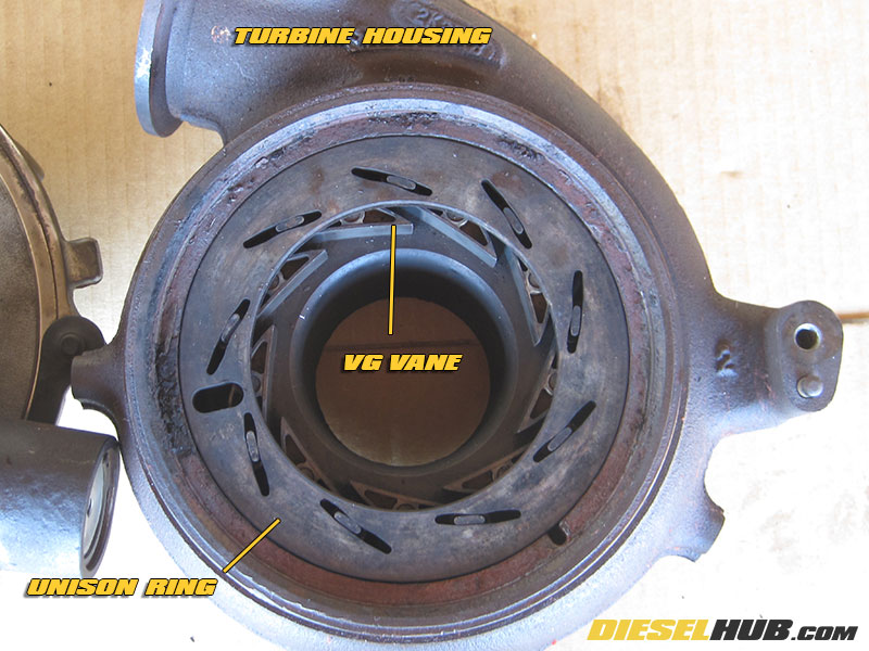
Restricted variable geometry vane movement is a common, reoccurring complication found in all model years of the 6.0L Power Stroke. Soot and ash buildup in the turbine housing has a tendency to reduce, if not completely eliminate movement of the unison ring and VGT vanes. When this occurs, various turbocharger performance conditions may arise and the only solution is to remove the turbocharger and manually clean the VGT system.
6.0 Power Stroke VGT Turbo Diagnostics & Troubleshooting
Stuck or sticking VGT vanes will often, but not always sets a DTC (CEL) related to turbocharger performance (P132B, P2263 for example). The most common insight into possible stuck/sticking VGT vanes is excessive turbocharger lag, particularly during heavy off-idle acceleration or freeway merging. In such instances, the turbocharger will experience severe lag and fail to build boost at low engine speeds. The following series of tests can be used to narrow down the source of driveability concerns related to turbocharger performance. A diagnostic tool with enhanced PID reading capability and actuation features is necessary for certain test procedures.
Remove and inspect the condition of the EGR valve - a clogged EGR valve can affect VGT operation. If any EGR related DTCs are present, repair the EGR system prior to diagnosing turbocharger concerns.
Visually inspect the condition of all CAC/intercooler boots and replace worn, cracked, or otherwise damaged boots. Before diagnosing the VGT system, verify that the problem is not related to a boost leak on the compressor side of the turbocharger. CAC boots tend to degrade as a result of oil from the crankcase ventilation system settling in the boots.
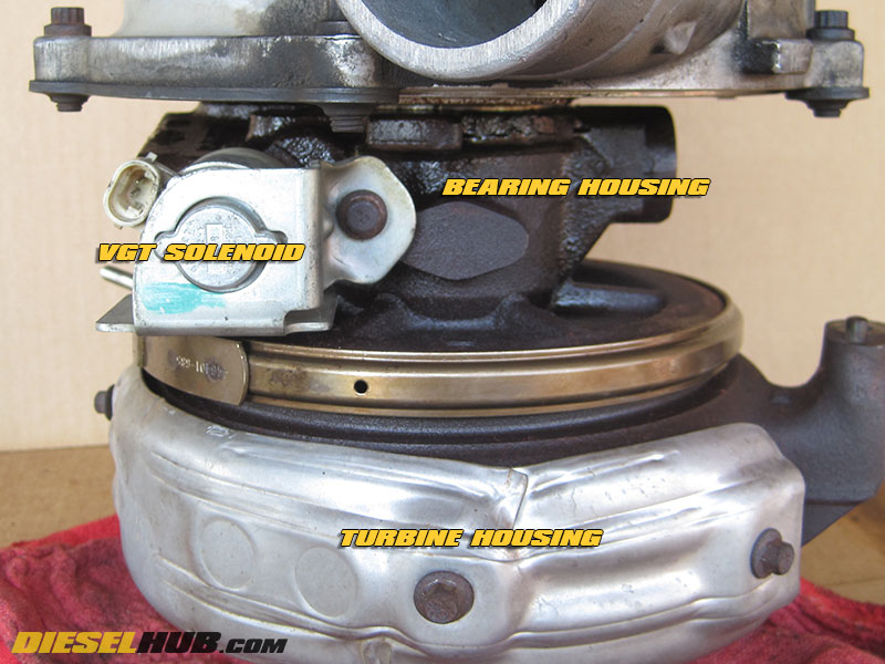
Test the VGT solenoid with a digital multimeter. After removing the solenoid connector, measure the resistance across the two pins. Ford's spec is 3.42 - 4.18 Ω (Ohms) when engine oil temperature (EOT) is at 73° F. If the resistance is out of spec, replace the VGT solenoid and check for further driveability concerns. If the solenoid measures within spec or a problem with the VGT system persists after replacement, you have at least ruled out the VGT solenoid as the culprit and the problem is more likely than not with the mechanics of the VGT components.
An audible VGT test can be performed using a diagnostic system (AutoEnginuity, for example) to manually command the VGT system. With the diagnostic system active, run the engine and command the VGT to the "closed" position, or an 85% duty cycle. The turbocharger should make a hissing or whistling noise. Next, command the VGT to the "open position, or a 15% duty cycle. Noise from the turbine side of the turbocharger should subside. If there is no change in sound characteristics when the VGT vane position is commanded from the open to closed position, the vanes are likely stuck and the turbocharger should be removed and cleaned.
A manifold gauge pressure (MGP) test is the most optimal method for testing VGT function, as it measures turbocharger boost pressure with respect to VGT vane position. Before performing the test, allow the vehicle to warm up for several minutes - results may be most accurate on an engine at operating temperature. With an enhanced diagnostic system, perform the following test procedures:
1) Set up the system to monitor exhaust back pressure (EBP) and manifold gauge pressure (MGP). 2003 and 2004 MY trucks that have had the 06E17 flash update use an inferred EBP value and therefore this PID is not available and can be ignored.
2) With transmission in park, set the engine speed to 1,200 rpm
3) Command EGR duty cycle to 0%
4) Command VGT duty cycle to 15% ("open" position), record MGP & EBP
5) Command VGT duty cycle to 85% ("closed" position), record MGP & EBP
6) Compare the results with Ford spec:
VGT Position |
Duty Cycle |
EBP Reading |
MGP Reading |
Open |
15% |
< 7.3 psi |
< 0.45 psi |
Closed |
85% |
< 7.3 psi |
> 0.87 psi |
Note - values may not be applicable to trucks with aftermarket intake and/or exhaust systems.
If EBP is not within spec, replace/clean the EBP sensor and repeat the test. Additionally, a minimum 22 psi MGP should be recorded at 3,300 rpm in 3rd gear under WOT (wide open throttle). If recorded values do not fall within spec, the VGT system is not functioning properly. Disassembly and cleaning of the VGT components is advised.
Turbocharger Reassembly Parts List
Description |
Part Number(s) |
Remarks |
GT3782VA bearing & seal service kit |
Garrett 740659-0010 |
[1] |
Turbocharger master reinstall kit |
[2] |
|
Unison ring |
[3] |
|
VGT vanes |
[3] |
|
Compressor housing to backing plate o-ring |
Garrett 403069-0252 |
[4] |
VGT solenoid |
[5] |
|
High temperature nickel anti-seize |
[6] |
|
3M Roloc arbor |
[7] |
|
3M Roloc conditioning discs |
[7] |
[1] - Includes bearings, thrust washer, oil ring seals, and various components required for turbocharger overhaul; does not include compressor housing to backing plate o-ring
[2] - Required to reinstall turbocharger; includes pedestal bolts and oil feed gasket
[3] - Inspect and replace if bent/damaged; clean wit Roloc conditioning discs as required
[4] - Not included in service kit, must purchase separately; do not recommend reusing
[5] - Replace as required; if in good working order, replace o-rings
[6] - Rated for temperatures in excess of 2,400° F, prevents the VGT vanes and unison ring from seizing inside the turbine housing
[7] - Recommend 3M Roloc product line, but other conditioning discs and equivalent products can be used; do not substitute for sandpaper or other harshly abrasive materials
How to Disassembly & Clean the Unison Ring/VGT Vanes on a 6.0 Power Stroke Turbo
Click any thumbnail to view high resolution fullsize image w/ addition details (where applicable)
• Disconnect both negative battery cables.
• Remove the turbocharger from the vehicle and place it on a clean workbench. For step-by-step turbocharger removal procedures, see: 6.0L Power Stroke turbocharger removal and installation
• Remove the VGT solenoid and turbine housing heat shield. Both require an 8 mm socket - the solenoid must be a 12 point socket.
• Using a scribe or paint marker, draw a reference line across the turbine housing and one edge of the turbine V-band clamp. You will need to use this reference line to orient the clamp during re-installation so that it is positioned in the exact same location that it was removed.
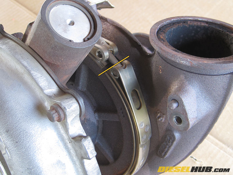
• Loosen and then remove the nut from the turbine housing to bearing housing flange V-band clamp (11 mm deep socket). Removing the bolt from the clamp entirely will make the clamp easier to manipulate in subsequent steps.
• Position the clamp off of the turbine housing and onto the bearing housing such that the flange/groove between the two sections is visible.
• Generously apply penetrating lubricant (PB Blaster, WD-40, etc) to the turbine housing groove and allow to sit for at least several minutes before continuing.
• Position the turbocharger on a workbench so that the turbine housing outlet (exit to downpipe) is face down on the work space and the compressor inlet is pointing upwards.
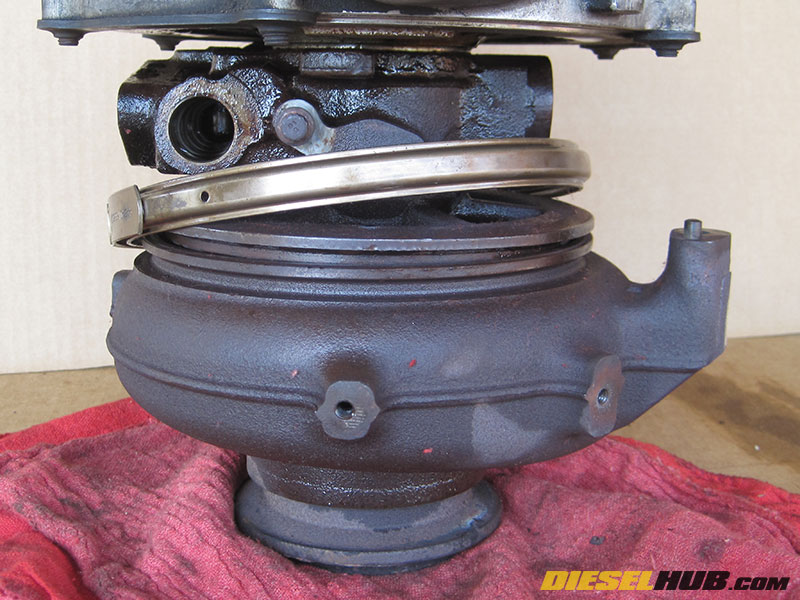
• Tilt the turbocharger slightly to one side and tap the turbine housing with a dead blow hammer - do not use an iron hammer as you may damage the turbine housing. Repeat the procedure until a gap begins to form between the turbine housing and flange, rotating the turbocharger after a few taps and working 360 degrees around the housing. If the housing fails to separate, increase the force of your blows.
• Once the gap opens up wide enough that a pry bar or large flathead screwdriver can be inserted, carefully work around the housing until the two halves separate completely. Work the groove open evenly around the entire circumference in small increments so that the turbine housing does not contact the turbine wheel during disassembly. Separating this parts may require patience, as they tend to be extremely stubborn. Do not be afraid to reapply penetrating fluid and let the parts soak.
• When the housing eventually separates, ensure the turbine outlet is face down on the workbench so that the unison ring and VG vanes do not fall out of place.
• With the halves separated, you can test VG operation by rotating the unison ring.
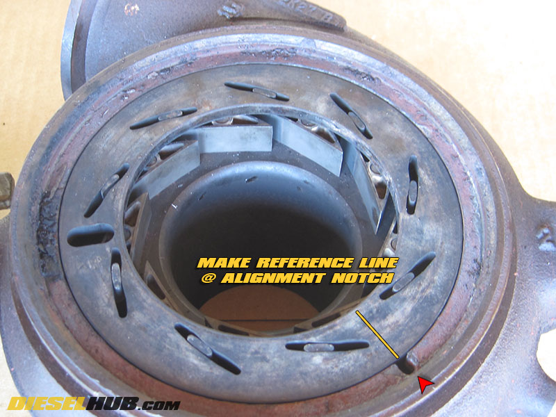
• Index the unison ring with a scribe by making a reference line across the unison ring where the alignment dowel fits into the turbine housing so that it can be reinstalled in the correct position. If you forget this step or accidentally remove your reference line while cleaning, we'll show you how to install the unison ring in the correct position without a reference line.
• Remove the unison ring followed by the individual VG vanes. Place the vanes in a container filled with penetrating lubricant and allow to soak for several minutes in order to loosen any heavy deposits.
• Clean the turbine housing and unison ring. The preferred method is using 3M's Roloc (alternatively Scotch-Brite) surface conditioning discs attached to a pneumatic die grinder. These discs are 2" in diameter, so you will have to trim several discs down to 1" diameter in order to clean the surface around the VG vane pins.
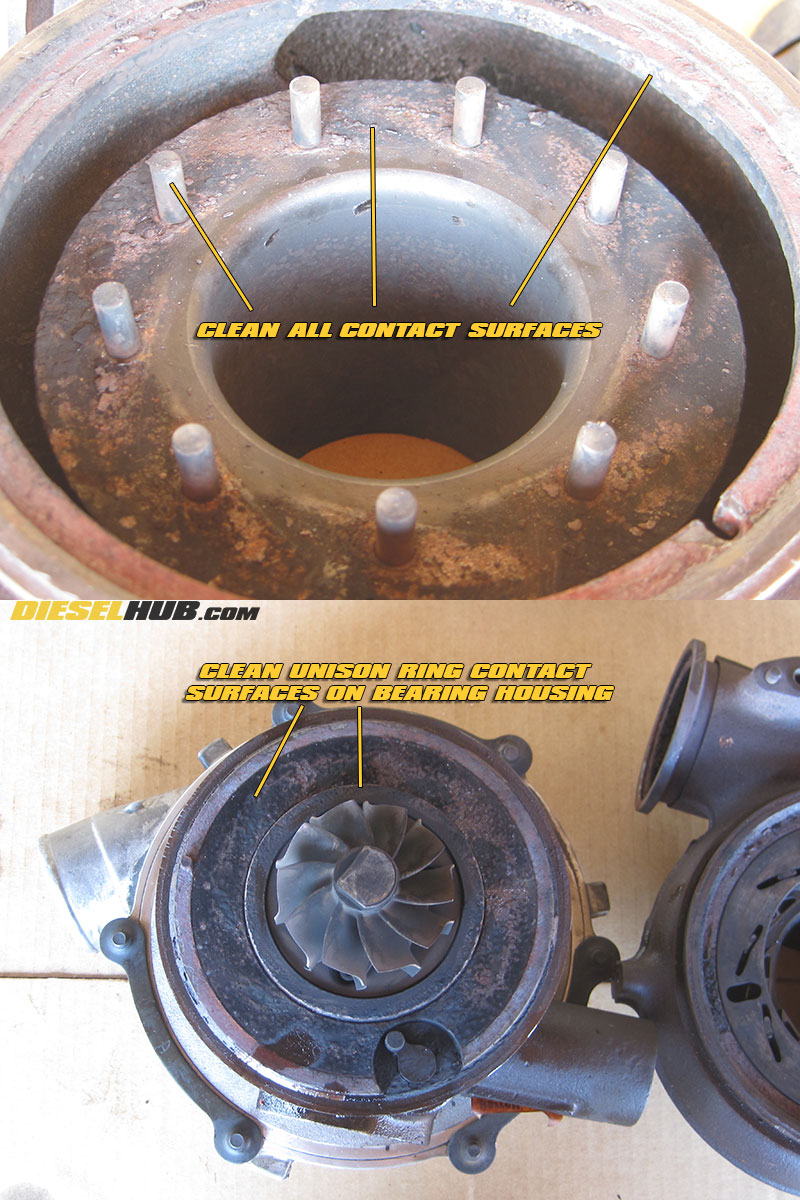
• Thoroughly clean the unison ring, any surfaces that may interfere with the unison ring (don't forget the bearing housing side), the VG vane pins, all contact surfaces for the VG vanes, and any build up on the bearing housing and turbine housing mating surfaces. If you see anything that may interfere with VGT operation, clean it thoroughly!
• Clean the individual VG vanes by hand using a Scotch-Brite disc or equivalent means - do not use sandpaper, harsh abrasives, or power tools on the VG vanes. Clean deposits from pinholes with a copper/brass wire brush.
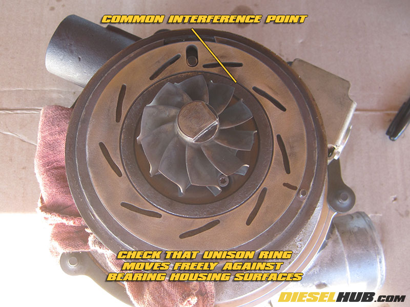
• Once all the surfaces have been cleaned, install the VG vanes and unison ring, then check for proper actuation and clearance. Verify that unison ring moves freely around the flange on the bearing housing below the turbine wheel (see image). If any interference or clearance issues are detected, continue cleaning.
• Disassemble the turbine housing and clean the housing, VG vanes, and unison ring with brake cleaner or an equivalent solvent, removing any debris that may have accumulated while cleaning.
• Clean the bearing housing side with compressed air - do NOT use a solvent.
IF you failed to index the position of the unison ring within the turbine housing, or your reference line was accidentally removed while cleaning, the following procedures will allow the unison ring to be installed correctly. You may skip these steps if your unison ring has a reference line that positions it correctly within the turbine housing.
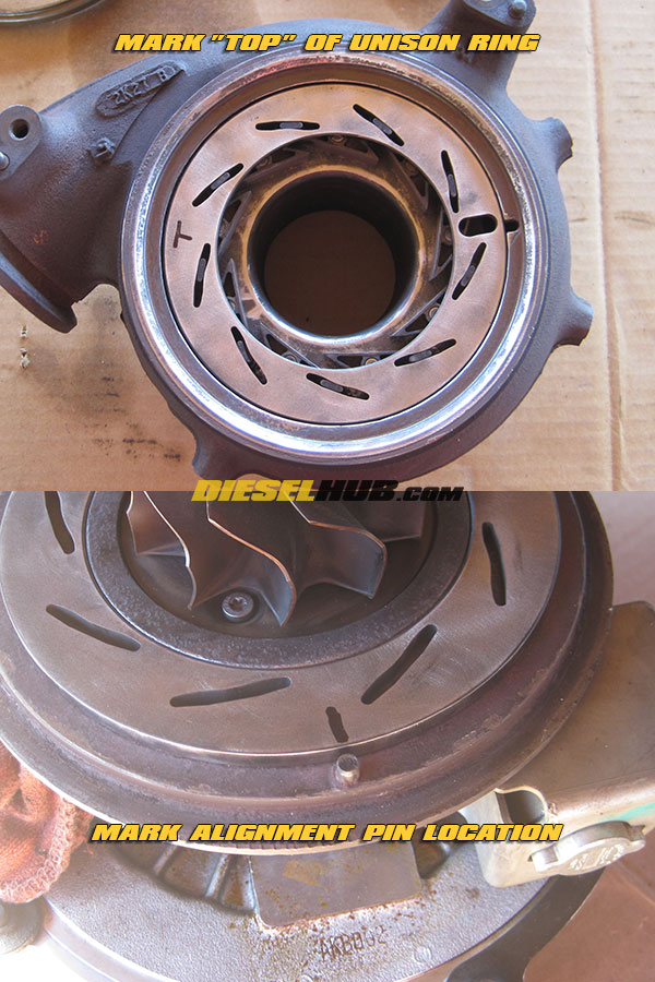
1) Install the VG vanes onto the pins in the turbine housing followed by the unison ring - you will have to continuously adjust the vanes until their control slide falls into the corresponding slot on the unison ring. Once you've installed the unison ring, mark the surface facing you with a "T"; for our purpose, we're calling this the top of the unison ring.
2) Remove the unison ring from the turbine housing and place it against the contact surface of the bearing housing, aligning the VG control arm pin into the corresponding slot on the unison ring. The "T" you marked in the previous step should be facing the contact surface of the bearing housing and should NOT be visible.
3) Move the unison ring so that the VG control arm is roughly centered (centered between the right and left positions). Mark the location of the protruding alignment pin on the bearing housing onto the unison ring (see image).
4) Extend your new reference line to the top of the unison ring. The unison ring can now be positioned correctly within the turbine housing by simply aligning this reference line with the alignment hole in the turbine housing.

• Lightly coat the following with high temperature anti-seize:
- Unison ring contact surfaces and VG vane slots (including contact surfaces on the bearing housing)
- Contact surfaces between turbine housing and VG vanes
- VG vane pinholes and VG vane pins
-
Mating surfaces between bearing and turbine housing (outer flange)
- VG control arm pin
Note - a high temperature anti-seize is required. Ford's anti-seize formula is spec'd to 2,400° F.
• Assembly the VG vanes and unison ring (unison ring must be installed in the correct position using your reference line). Cycle the vanes through the fully open and closed positions several times, then remove any excess anti-seize.
• Slide the turbine housing V-band clamp over the bearing housing flange.
• Reinstall the turbine housing to the bearing housing with the turbine housing face down such that the unison ring and VG vanes cannot fall out of place. You will need to align the alignment pin on the bearing housing into the corresponding notch in the turbine housing as well as ensure that the VG actuator pin is correctly inserted into the unison ring slot (you may use a small pick to orient the unison ring until the pin and slot align).
• Maneuver the turbocharger so that the groove between the bearing and turbine housings is roughly the same on all sides. Lightly tap around the entire circumference of the bearing housing with a dead blow hammer to begin to seat the housing. After a series of taps, verify that the turbine/compressor wheel spin freely; if the wheels are bound, the housing is contacting the turbine wheel and not seating straight. If this occurs, separate the housing and start over or attempt to even out the groove. The housing needs to be seated evenly such that the turbine wheel does not bind. It may take several attempts to seat the housing evenly.
• Increase the force of your blows as necessary to continue to seat the housing. Ultimately, you'll want to seat the housing until the groove is eliminated and the two sections are fully seated; do not neglect to check for binding of the turbine wheel during this process.
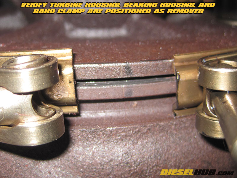
• Once the groove has closed, install the V-band clamp around the flange and position it to the location from which it was removed using your reference line. Torque the turbine housing clamp to 160 in-lbs, then loosen and re-torque to 50 in-lbs. Tap the perimeter of the turbine housing with a dead blow hammer several times, verify there is no binding of the turbine wheel, then torque the clamp to 150 in-lbs. Check the turbine wheel is not bound one final time.
• Reinstall the VGT solenoid. Torque bracket retaining bolt to between 15 and 18 ft-lbs.
• Reinstall turbocharger and test for VGT function. For turbocharger installation procedures, see: 6.0L Power Stroke turbocharger installation guide