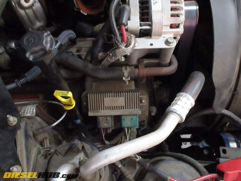
The glow plug control module (GPCM) on a 6.0L Power Stroke is located on the passenger side valve cover near the front of the engine. For late 2004 through 2007 model years, it is in the vicinity of the ICP sensor. The location is identical for 2003 and early 2004 engines, however the ICP reference is not applicable since the sensor on these model years is located behind the turbocharger. The aluminum GPCM has two large electrical connectors, one of which is black and one of which is green.
Glow plugs should be replaced with genuine Ford units. The part number is Motorcraft ZD-12 for 2003 to early 2004 model years and Motorcraft ZD-13 for late 2004 to 2007 model years. Early glow plugs are longer and cannot be used in later engines as the piston design is different; engine damage will occur. According to Ford, the cutoff date is September 29th, 2003. This is the engine build date, not the vehicle assembly date.
6.0L Power Stroke Glow Plug Operation
There is a single glow plug for each cylinder and therefore 8 glow plugs total. A harness spans the entire bank (4) of glow plugs and supplies power. There are two separate glow plug cycles; the main cycle draws a considerable load from the battery and occurs while the glow plug preheat lamp is illuminated in the dash (alternative called the "wait-to-start" light). When the glow plug preheat lamp is no longer displayed, the glow plugs may remain on in a secondary cycle, drawing less battery current but maintaining a "warm" state. The entire glow plug cycle (primary and secondary) will last a maximum 120 seconds, not including any post-cycle activation that occurs once the engine has been started. Post-cycles are generally very short activation periods which aid combustion in cold weather. The glow plug preheat lamp will illuminate briefly as these events occur, so there's no reason to be alarmed that the glow plugs are activating after the engine is running.
The length of time that the glow plugs are cycled depends on engine oil temperature and altitude; the PCM does not take into account engine coolant temperature, intake air temperature, or ambient temperature. As previously stated, the system will cycle for a maximum 2 minutes (120 seconds), less any post-cycle events. Because glow plugs draw a substantial electrical load, battery condition is directly related to starting ease. A battery that is borderline "good" may not suffice and a battery that registers near "perfect" is typically necessary to properly cycle the glow plug system and maintain engine speed during cranking. Battery voltage information is provided in the troubleshooting section below.
6.0L Power Stroke Glow Plug Troubleshooting & Diagnostics
Battery condition is imperative so checking battery voltage is the first step in diagnosing a hard start, long crank, or rough start condition. A "perfect" battery should read 12.5 to 12.7 volts. The closer the battery reads to 12.0 volts, the less charged it is. In fact, many engine's will not start with a battery that only registers 12.0 volts (or less). Engine cranking speed is important to 6.0L and 7.3L Power Stroke diesels because they must produce a minimum oil pressure in the high pressure system in order to fire an injector; a slow crank condition often points to a bad battery. Additionally, a slow cranking engine generates less heat from compression in the cylinder and this heat dissipates more rapidly. Always disconnect the negative battery cables before checking battery voltage, as it is ideal to isolate the pair of batteries. If one battery has a bad cell or is weak, it will pull the total system voltage down. Batteries that will not charge into the 12.5 to 12.7 range (that won't "accept" a full charge) should be replaced. Batteries may also be load tested free-of-charge at most auto part stores; this test checks battery condition with more precision.
Exhaust smoke is a useful indicator in what is happening during a hard start, no start condition. White smoke is raw fuel that it not combusting in the cylinder and indicates that there is not enough heat being generated to permit auto-ignition. Black smoke is partially burned fuel and typically points to a rich condition. It is normal, even typically for a cold 6.0 to emit a small mass of white or black smoke upon starting, particularly in cold weather. However, a constant plume of white smoke while cranking indicates that fuel is being injected into the combustion chamber, but ignition is not occurring - this is a strong indicator of a glow plug system problem. In some instances, no smoke may be more worrisome as it indicates fuel is not being injected into the combustion chamber; a high pressure oil system, extremely slow crank, or electrical issue is likely to blame in such circumstances (i.e. FICM would be a common culprit).
A GPCM issue almost always triggers a DTC and MIL (malfunction indicator lamp, check engine light), whereas a faulty glow plug or series of glow plugs may not set a DTC. If there are no DTCs stored relating to the glow plug system the GPCM can comfortably be ruled out as the root problem, at least in short run. Searching for a faulty glow plug is not particularly burdensome and is outlined in the steps below.

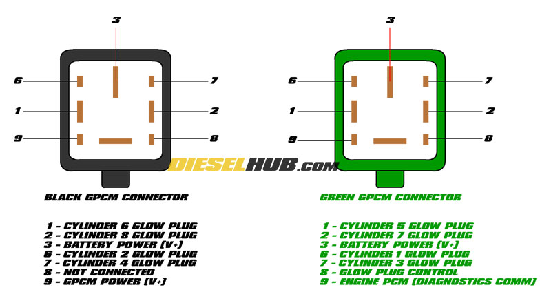
6.0L Power Stroke glow plug control module (GPCM) connector pinouts.
0.5 to 2.0 Ω (ohms) of resistance between the appropriate pin and negative battery cable is within the acceptable range.
A faulty glow plug should measure considerable outside this range, up to infinity (indicating an open circuit).
Click any thumbnail to view high resolution fullsize image w/ addition details (where applicable)
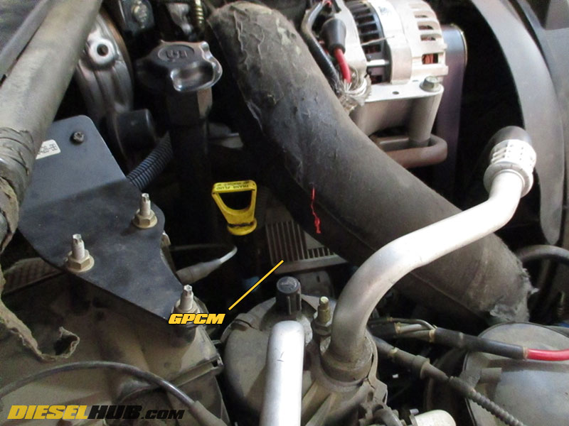
• Glow plugs can be checked individually through each of the two GPCM connectors. The GPCM is located on the passenger side valve cover, behind the alternator and underneath the hot-side intercooler tube.
• Disconnect both negative battery cables.
• Remove the intercooler tube to access the GPCM. If the truck is a late 2004 or newer model year (ICP sensor on the passenger side valve cover), disconnect the ICP sensor so that the GPCM connectors can be accessed.
Note - The orientation of the GPCM pictured represents 2003 to early 2004 model years. On late 2004 and newer model year engines, the GPCM will be positioned in the same location but rotated 90° clockwise with the connectors pointed at the firewall. The GPCM is an identical part on all engines.
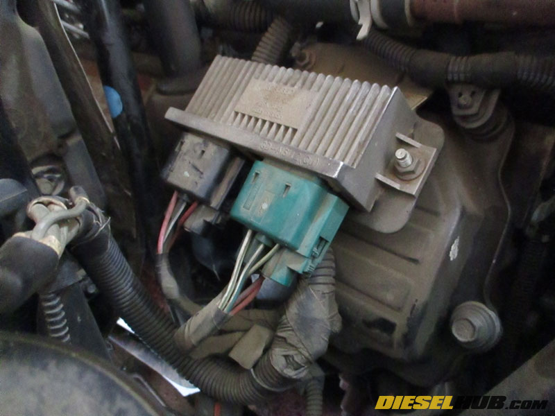
• The GPCM, regardless of model year, has two large connectors; one is black and one is green. Remove the connectors by depressing the locking tab and pulling away from the GPCM.
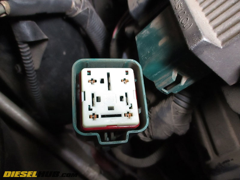
• Use a digital multimeter to test resistance in each individual glow plug circuit of the green connector by probing the correct terminal with one lead and the negative battery cable with the other. Factory spec is 0.5 to 2.0 Ω (ohms) of resistance for a properly functioning glow plug.
See pinout diagram above

• Test the resistance in each individual glow plug circuit of the black connector as outlined in the previous step.
See pinout diagram above
• Any glow plugs that fail the aforementioned test should be tested at the glow plug itself by measuring resistance across the terminal (top) of the glow plug and the negative battery cable in order to verify that it is the glow plug and not related to a problem with the GPCM harness.
• To access the glow plugs, remove the inner fender and locate the glow plug busbar. The busbar runs longitudinally along the bank of glow plugs and is several inches above the exhaust manifold.