The following procedures are based on a 1996 model year 7.3L Power Stroke. 1994.5 and 1995 model years use an identical fuel filter housing while 1996 and 1997 model years share a slightly different fuel filter housing. The small differences between the two styles include port locations and the fuel pressure regulator (FPR) filter screen. The following procedures serve as a guide for both styles, although all images refer to the 1996 - 1997 style housing.
7.3 Power Stroke Fuel Bowl Parts List (1994.5 - 1997)
Part Description |
Part Number(s) |
Remarks |
Fuel filter housing assembly |
[2] |
|
Fuel bowl seal kit, 1994.5 - 1995 models |
Ford F5TZ-9157-A |
[1] |
Fuel bowl seal kit, 1996 - 1997 models |
Ford F5TZ-9157-BA |
[1] |
Fuel pressure regulator rebuild kit |
Ford F5TZ-9K061-A (w/ Federal emissions) |
[1] |
Fuel pressure regulator screen repair kit |
[1] |
|
Fuel pressure regulator pre-filter |
Ford F5TZ-9150-A |
[1],[4] |
Fuel bowl standpipe |
[2] |
|
Fuel bowl wiring harness |
[2] |
|
Fuel bowl heater |
[2] |
|
Fuel heater/thermostat through connector |
Ford F4TZ-9J294-A |
[2] |
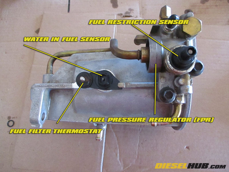
Water-in-fuel sensor |
[2] |
|
Fuel restriction sensor |
[2] |
|
Fuel filter |
[1],[3] |
|
Fuel bowl cap |
[2] |
|
Pressure hose kit (basic install kit) |
[1],[5],[6] |
|
Hose, fuel pressure regulator to fuel tank return line |
Dieselply DP-163301 |
[1],[6] |
Hose, top of fuel pump to filter bowl |
Dieselply DP-163401 |
[1],[6] |
Hoses, driver side fuel pump port to fuel tank hard-line |
Dieselply DP-163502 |
[1],[6] |
Bypass hose, fuel pressure regulator to fuel bowl |
Dieselply DP-163601 |
[1],[4],[6] |
Hose, fuel drain valve to drain hard-line |
Dieselply DP-163201 |
[2] |
Passenger side fuel return hose |
[2] |
|
Driver side fuel return hose |
[2] |
|
Fuel drain valve assembly |
[2] |
[1] - Replacement required or highly recommended; do not reuse part(s)
[2] - Replace as needed if part is damaged or otherwise compromised
[3] - Fuel filter should be replaced after fuel bowl is reinstalled
[4] - For 1994.5 and 1995 model year fuel bowls only; Ford part is no obsolete and no longer manufactured
[5] - Kit includes all pressure hoses required to reinstall fuel bowl; KFL-33, KFL-34, KFL-35
[6] - OEM Eaton/Continental hoses packaged under the Dieselply brand; these are identical to the Ford/Motorcraft parts but include hose clamps
[7] - Updated high temperature hose, replace only as required
1994 - 1997 7.3 Power Stroke Fuel Bowl Rebuild Procedures
Click any thumbnail to view high resolution fullsize image w/ addition details (where applicable)
• Remove the fuel filter housing assembly and place it on a workbench. See: 7.3L Power Stroke fuel filter housing removal & installation procedures
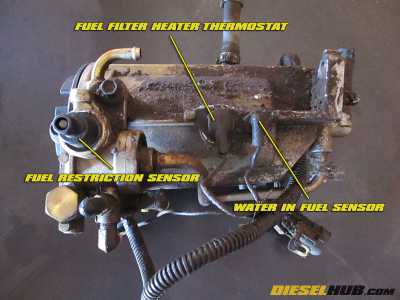
• Carefully disconnect the electrical connectors from the fuel filter housing heater and water-in-fuel sensor (see image for details).
Note - the fuel heater electrical connector can be stubborn. You may need to gently prey side to side. A replacement harness is somewhat expensive, so do not get impatient and break it.
• Remove the wiring harness from the fuel filter assembly by maneuvering the connectors one-at-a-time through the opening at the bottom of the housing. This harness is to be cleaned and reused if it is not damaged.
• Remove the fuel filter cap/lid.
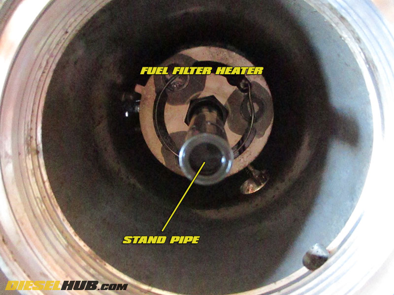
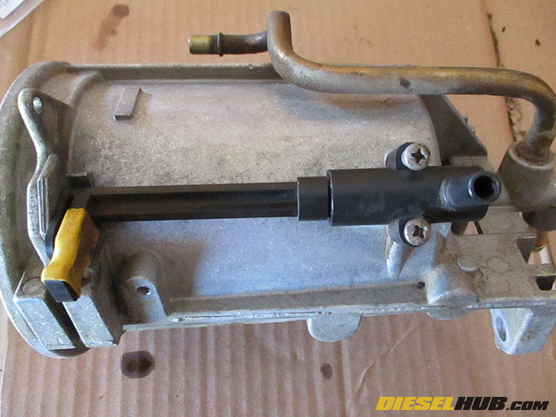
• Remove the fuel filter standpipe using a 7/8 inch crowfoot wrench and socket extension. Rotate it clockwise to loosen, it is left hand thread. A flare nut crowfoot wrench is preferred as it will eliminate the possibility of damaging the plastic hex nut molded into the base of the standpipe. Remove by hand once it has been broken loose and be careful not to damage the fuel heater element.
• Carefully tilt the fuel heater and disconnect the terminal from the connector that passes through the body of the fuel filter housing using a pair of long needle-nose pliers.

• Remove the water in fuel sensor using a 9/16" socket.
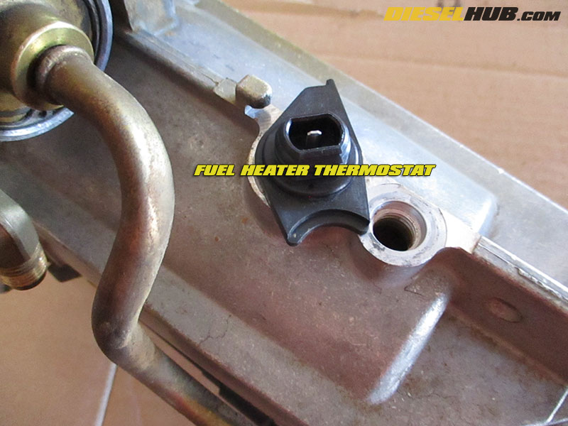
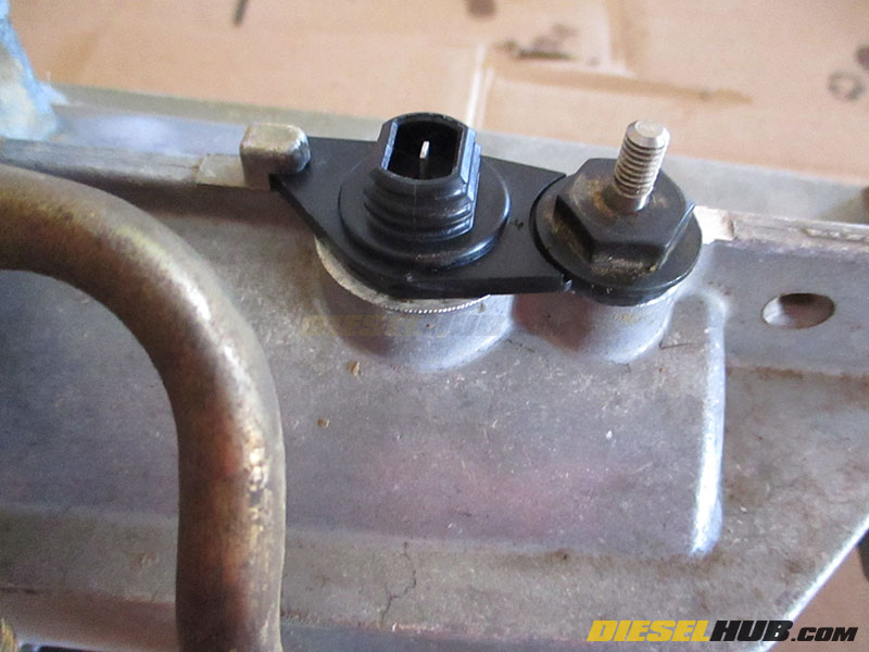
• Remove the fuel heater thermostat/connector by first rotating it clockwise until the black plastic tab clears the corresponding aluminum tab on the fuel filter housing, then pulling upwards. It may be stubborn and require gentle prying from side to side as the o-ring has to collapse to pass through the hole in the fuel filter housing.

• Remove the water drain valve using a Phillips screwdriver.
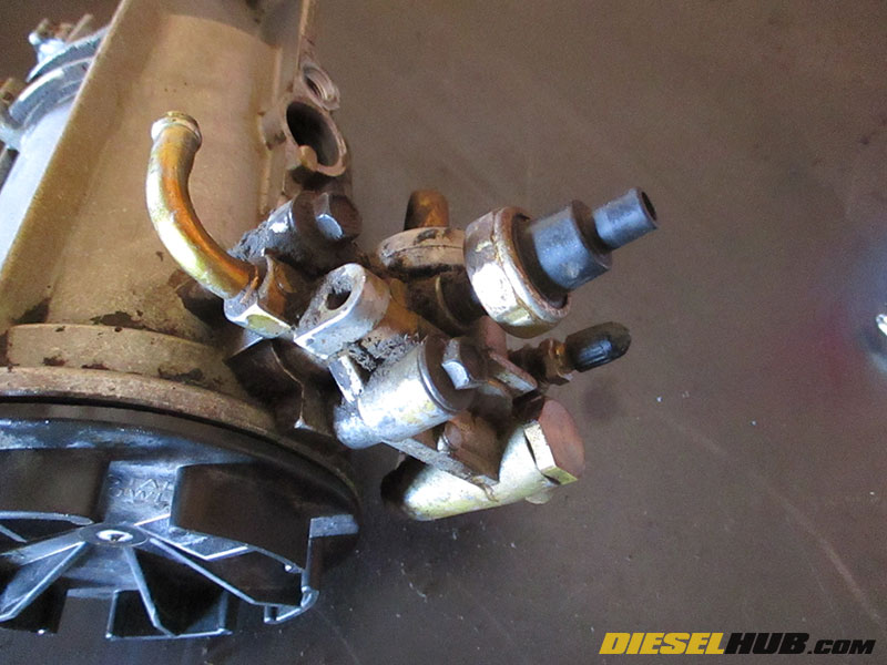
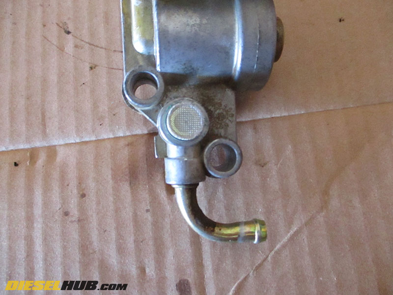
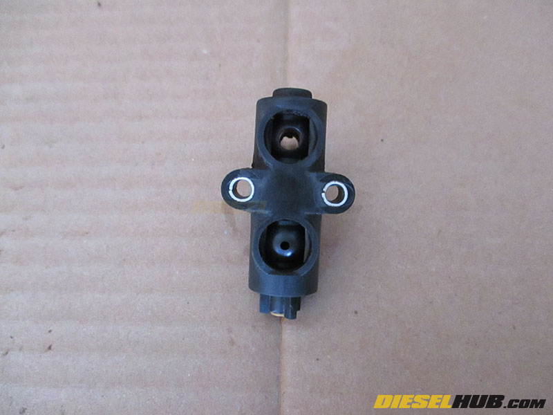
• Remove the fuel restriction sensor. It is threaded into the fuel pressure regulator body on 1996 - 1997 model year engines (top of fuel filter housing) and fuel filter housing pressure line (bottom of fuel filter housing) on 1994 - 1995 model year engines. A 1-1/16 inch socket is necessary to remove it.
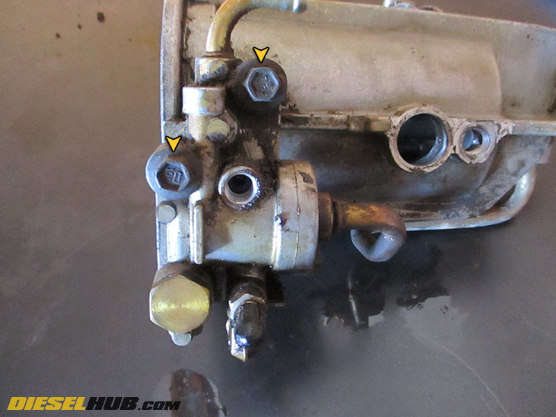
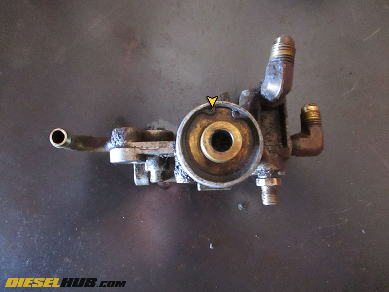
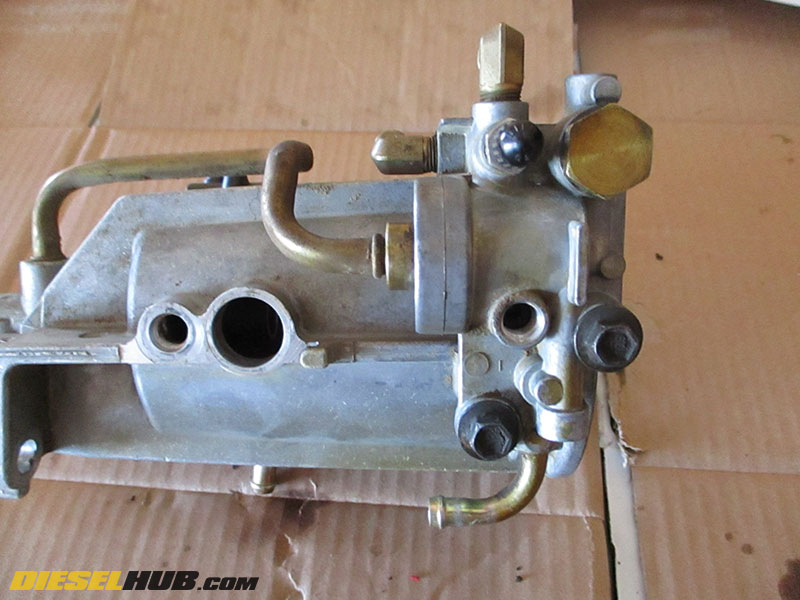
• Remove the fuel regulator body from the fuel filter housing using a 10 mm socket (2 bolts, see image).
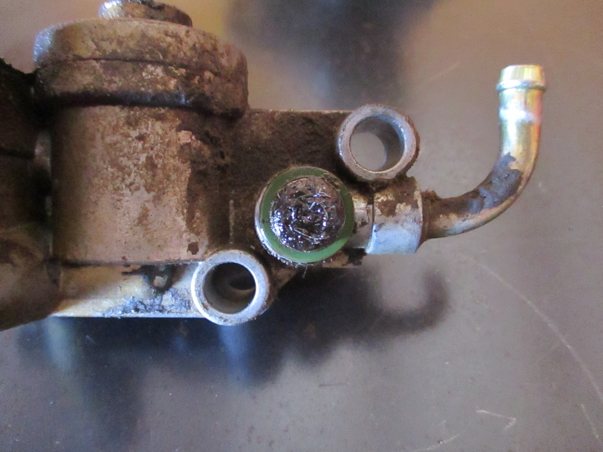
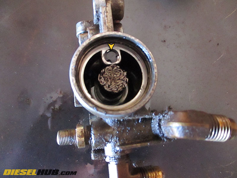
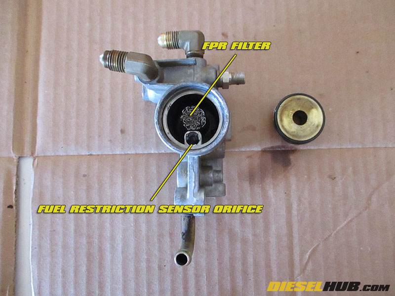
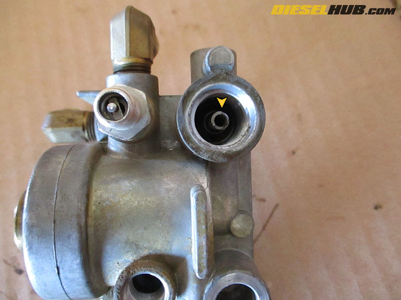
• There is a small screen located between the fuel filter housing and fuel regulator assembly. Refer to the image - this one is completely clogged. Behind the screen is the bleed orifice (white plastic component) followed by a small plastic check ball. Remove the screen, orifice, and check ball.
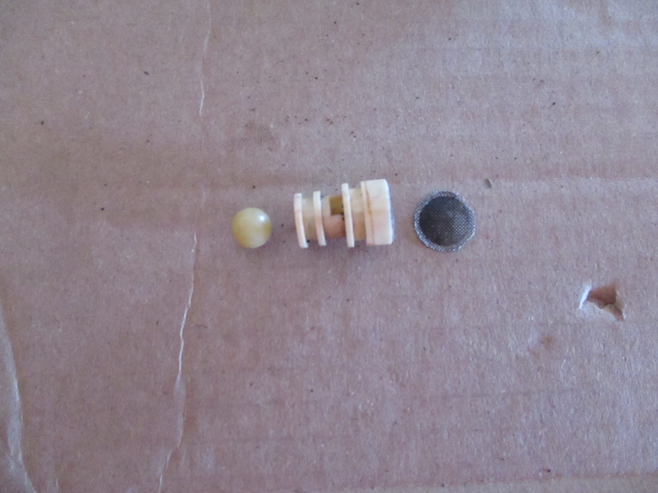
Note that the screen may or may not be attached to the bleed orifice, they tend to detach but can still be reused. Do not lose the check ball.
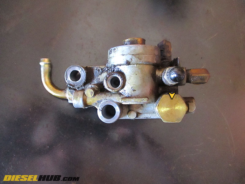
• Remove the fuel pressure relief valve using a 19 mm socket. Behind the brass nut is a spring and plunger; set them aside.
• Remove the snap ring from the fuel pressure regulator, then remove the brass cap.
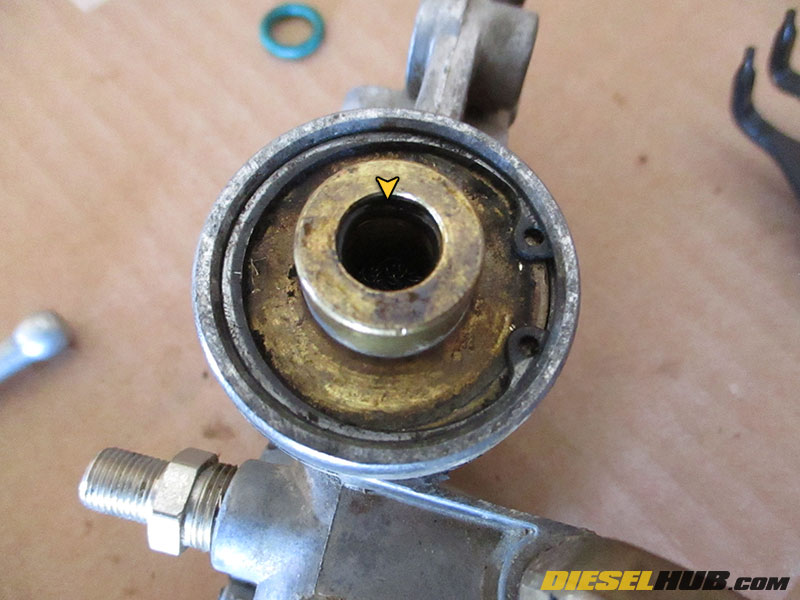
• Remove the plastic cap from the fuel restriction sensor port and set aside (see image for details). A small pick can be used to gently pry it upwards.
• Remove the metal filter screen from the fuel pressure regulator.
• Completely clean all metal interior and exterior components of the fuel filter housing and fuel pressure regulator assembly with a mild solvent or parts cleaner. Clean plastic components with a plastic safe electrical connector cleaner, not a harsh solvent. Ensure that every orifice is cleaned and debris free before reassembly.
IN ALL REASSEMBLY STEPS, LIBERALLY COAT EACH O-RING IN CLEAN MOTOR OIL BEFORE PRIOR TO INSTALLATION.
• Install the fuel screen into the fuel pressure regulator. Install the new o-ring on the fuel filter regulator cap.
• Carefully install the fuel filter regulator cap and snap ring. It is extremely easy to cut the o-ring during installation. To avoid this, keep the cap straight during installation so that it seats evenly.
• Replace the small o-ring in the top of the fuel pressure regulator. A pick is necessary to install the new o-ring, but be carefully not to cut it.
• Reinstall the fuel pressure relief valve with a new o-ring; do not overtighten.
• Install the check valve, then bleed orifice/screen. If this item has been replaced, the screen will be attached to the bleed orifice. If the original is being reused, install the bleed orifice into the fuel pressure regulator body and the screen into the fuel filter housing. The bleed orifice has (2) o-rings that must be replaced.
• Install a new o-ring in the opening between of the fuel filter housing where the bleed orifice/screen installs.
• Reinstall the fuel pressure regulator. Lightly coat the tip of the metal fuel line that inserts into the fuel pressure regulator with clean motor oil to help the o-ring seal. Do not overtighten fuel filter regulator to fuel filter housing bolts; torque to 100 - 120 in-lbs.
• Reinstall the fuel restriction sensor, torque to 35 - 45 in-lbs.

• Disassemble the fuel drain valve by first removing the two large o-rings that seal the valve to the fuel filter housing. Next, rotate the drain valve until the flat spot on the ball valves is visible through the two holes on the back of the valve. When these are lined up properly, the valve core can be removed from the drain valve body.
• At the top of the valve core is a white pin. To remove it, thread a small machine screw into the top and carefully extract. Beneath the pin is a check ball - do not loose it.
• Replace all o-rings, clean the drain valve components, and reassemble in reverse order.
• To reinstall the drain valve to the fuel filter housing, first verify that the two large o-rings that seal the valve to the filter housing are properly installed and coated in clean motor oil.
• Rotate the valve until the valve is in the open/drain position (you will see both holes in the ball valves from the back). Insert the drain valve lever so that it matches the open position on the fuel filter housing. Install the valve on the housing and tighten down the two Phillips headed bolts. Torque drain valve bolts to 20 - 25 in-lbs.
• Reinstall the fuel heater thermostat/connector assembly, then the water-in-fuel sensor with new o-rings. Torque water-in-fuel sensor to 18 - 24 in-lbs.
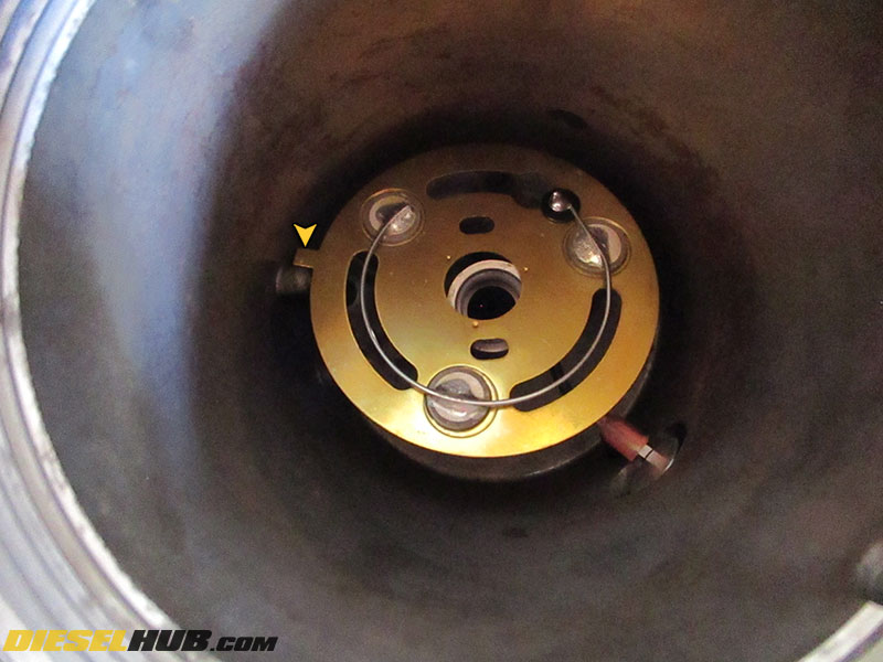
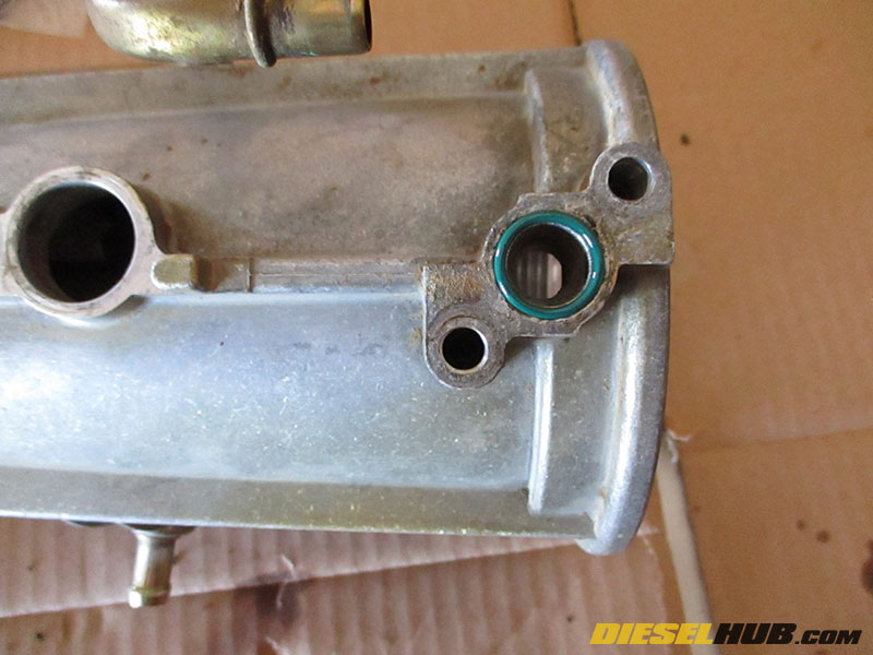
• Reinstall the fuel filter heater. Tilting it to one side allows access to the connector. The tab on the heater must rest against the corresponding tab cast into the fuel filter housing (see image) so that the heater assembly will not spin and become damaged when the standpipe is installed.
• Reinstall the standpipe by hand. Dip the threads in clean motor oil first. Recall that this is reverse (left-hand) thread. Snug it using a flare nut crows foot (as used in removal), but do not overtighten.
• Reinstall the wiring harness and plug in the fuel filter heater thermostat/connector and water-in-fuel sensor. Ensure that all electrical connectors/terminals have been cleaned.
Reinstall the fuel filter housing. See: 7.3L Power Stroke fuel filter housing removal and installation procedures