Crankshaft Position (CKP) Sensor Diagnostics
Crankshaft position sensor failures are quite rare for the 6.0L Power Stroke platform, but that should not be taken for granted as there remains the possibility of failure. Due to the sensors location and lack-of-access, the simplest way to isolate a CKP failure is to replace it following a P2617 and no-start condition or to monitor the appropriate PIDs and verify that the crankshaft and camshaft are or are not in sync. In instances where there is an obvious camshaft/crankshaft sensor communication error, always start with the camshaft position (CPS) sensor; it is easily accessible through the driver side fender well.
Note that DTCs P2614 (CPS) and P2617 (CKP) are always set simultaneously following a long crank condition. This does not immediately indicate that either sensor has experienced a fault and further diagnosis is required to isolate the cause of the long crank, no-start/hard start condition. If a DTC P2614 OR P2617 is set individually, it is more indicative a problem with that particular sensor or circuit.
The CKP sensor is a relatively inexpensive part to replace, but it is quite labor intensive and you can plan on spending the better part of a day navigating the spacial restraints around the sensor.
Associated Parts List
Description |
Part Number(s) |
Remarks |
Crankshaft position sensor (CKP) |
--- |
|
CKP sensor connector |
Ford 3U2Z-14S411-CGC |
[1] |
Engine oil filter |
[2] |
[1] - Inspect connector while separated from sensor; replace as necessary.
[2] - Recommend changing engine oil and lube oil filter after replacing the CKP sensor; this procedure may expose the engine crankcase to contamination.
How to Replace the Crankshaft Position (CKP) Sensor on a 6.0 Power Stroke
Click any thumbnail to view high resolution fullsize image w/ addition details (where applicable)
• Disconnect both negative battery cables.
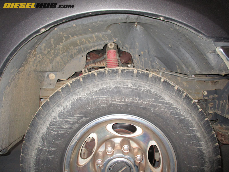
• Remove the inner fender from passenger side.
• Drain 2 to 3 gallons of engine coolant from the radiator. The petcock is located on the bottom of the radiator on the driver side. Drain the coolant into clean containers if you wish to reuse it.
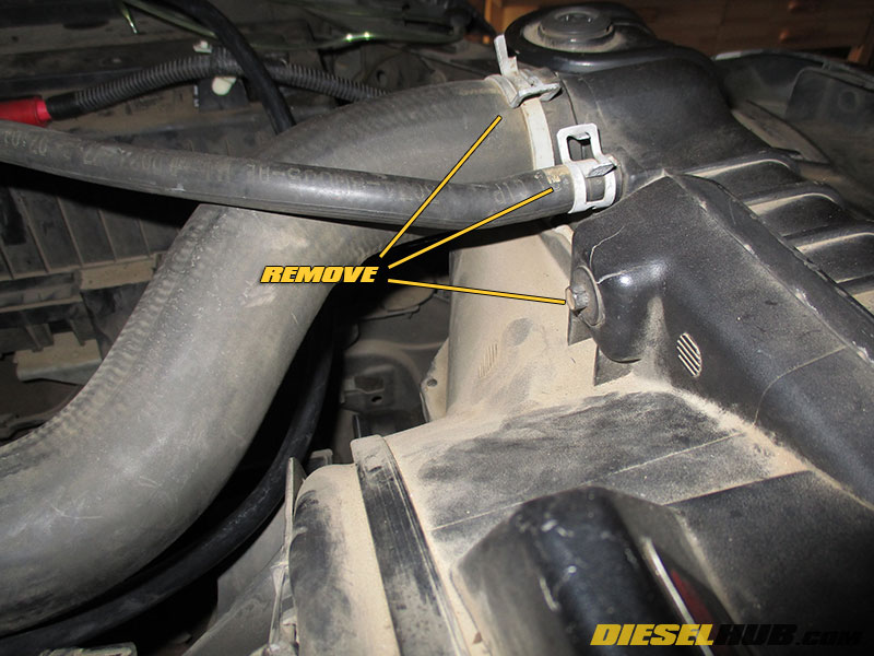
• Disconnect the upper radiator hose and degas tank hose from the top, driver side of the radiator.
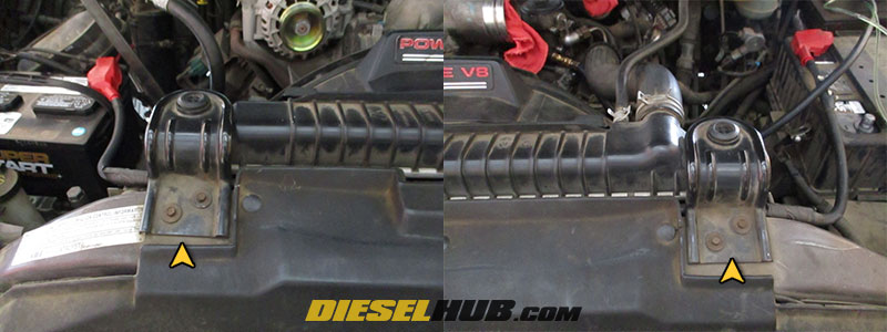
• Remove the radiator core support brackets with an 8 mm socket (two bolts per bracket).
• Remove the two (2) forward fan shroud bolts with an 8 mm socket.
• Remove the plastic clips that secure the positive battery cable to the radiator core support (the cable that connects the left and right batteries, it runs between the radiator and core support). Once free, position the cable out of the way by laying it on top of the engine.
• Remove the forward fan shroud by maneuvering it upwards.
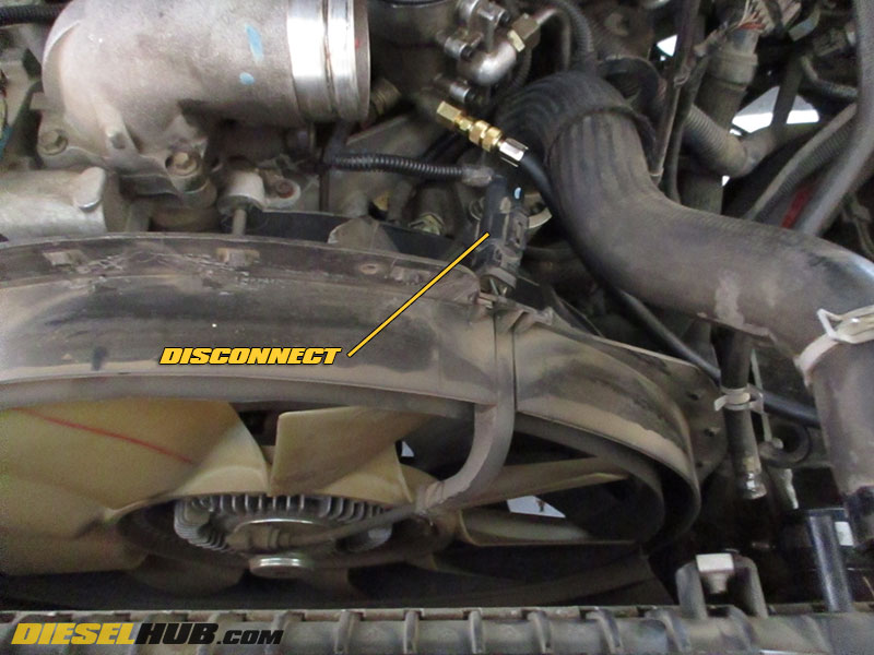
• Disconnect the electrical connector for the fan clutch.
• Remove the four (4) bolts and single nut securing the remaining fan shroud to the engine block; an extension will be required for the top bolts.
• With the fan shroud freed from the engine block, push it forward as much as possible - it does not need to be removed (which requires removal of the fan) and will catch the fan when pushed forward completely.
• Remove the serpentine belt from the AC compressor pulley. Relieving pressure from the belt tensioner and removing the belt from the alternator will suffice, there just cannot be any tension on the belt at the AC compressor before proceeding.
• Remove the ground clamp at the engine block and frame rail on the passenger side. You may also find it useful to disconnect/reposition various connectors and portions of the wiring harness to reach the AC compressor bolts.
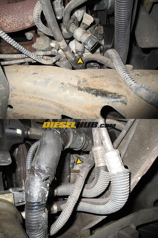
• Remove the three (3) AC compressor retaining bolts. The front bolts require a 10 mm wrench, while the rear bolt requires a 13 mm wrench (a ratcheting wrench will make quick work of it). The rear bolt is the most difficult to reach and patience is required to loosen it. There may not be ample space to remove the bolt entirely so once it is unthreaded from the engine block it can be left hanging in the compressor housing. You can see the head of the bolt and use a finger to align a wrench on it by looking through a hole in the cross-member spanning from frame rail to frame rail beneath the engine.
Note - 3rd AC compressor retaining bolt not pictured, no access for camera. It is located at the rear of the compressor between the compressor housing and engine block.
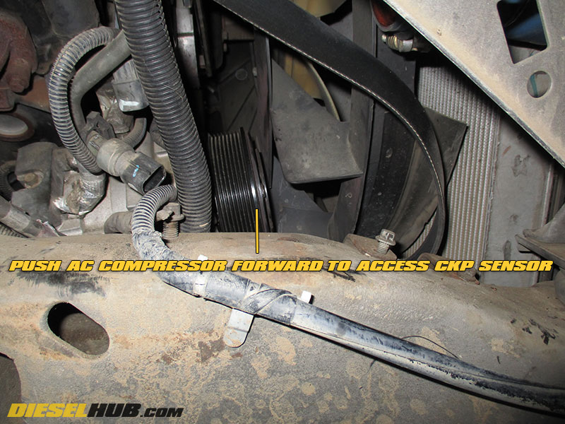
• With the AC compressor unbolted, push if forward against the fan shroud. This will create just enough room to see the crankshaft position sensor.
• Disconnect the connector from the CKP sensor, then remove the retaining bolt with an 8 mm socket. If you find the connector difficult to disconnect, you can alternatively remove the sensor first followed by the connector.
• The sensor can be accessed through the fender or from beneath the vehicle. Space is tight in either instance, and you'll find that a long pick is useful in removing the sensor from the engine block once it is unbolted.

• Coat the new sensor o-ring in clean motor oil, then Install the replacement CKP sensor and electrical connector.
• Reinstall the AC compressor, ground cables, fan shroud, serpentine belt, and all other items that were removed/disconnected during this process. Do not forget to refill the radiator with engine coolant.